see this link https://electrondust.com/2017/11/25/setting-raspberry-pi-wifi-static-ip-raspbian-stretch-lite/
Getting a Raspberry Pi to operate an old Bye Bye Standby (BBSB) RF 433 switch
Introduction
I decided to go and re-visit an old project. Getting my Raspberry Pi to switch some old RF plugs. I tried earlier this year or maybe last year and could never work it out.
This was prompted by a random google to this site. https://www.instructables.com/id/Control-RF-Outlets-With-Raspberry-Pi-3-433mHz-Rece/ and as I had all the “bits” I thought I would try again.
Installing Hassbian on the Pi
Things are never simple. Firstly getting a version of Hassbian onto the memory card seems to be much harder than I expected. The link in the article above was not to the latest version (Why would it be?) and looking further I found the install instructions here. https://www.home-assistant.io/docs/installation/hassbian/installation/. Once I had booted the Pi it seems that Hassbian was not corrected loaded so I upgraded in installation using “sudo hassbian-config upgrade hassbian”. This took a while to run (30+ mins). Then followed instructions and added
- Samba
sudo apt-get update
sudo apt-get upgrade
sudo hassbian-config install samba - WiringPi
sudo git clone git://git.drogon.net/wiringPi
cd wiring Pi
sudo ./build - Check using
gpio -v - Install RFSniffer
sudo git clone git://github.com/timleland/rfoutlet.git /var/www/rfoutlet
sudo chown root.root /var/www/rfoutlet/codesend
sudo chmod 4755 /var/www/rfoutlet/codesend
Pi Hardware – Receiver and Transmitter
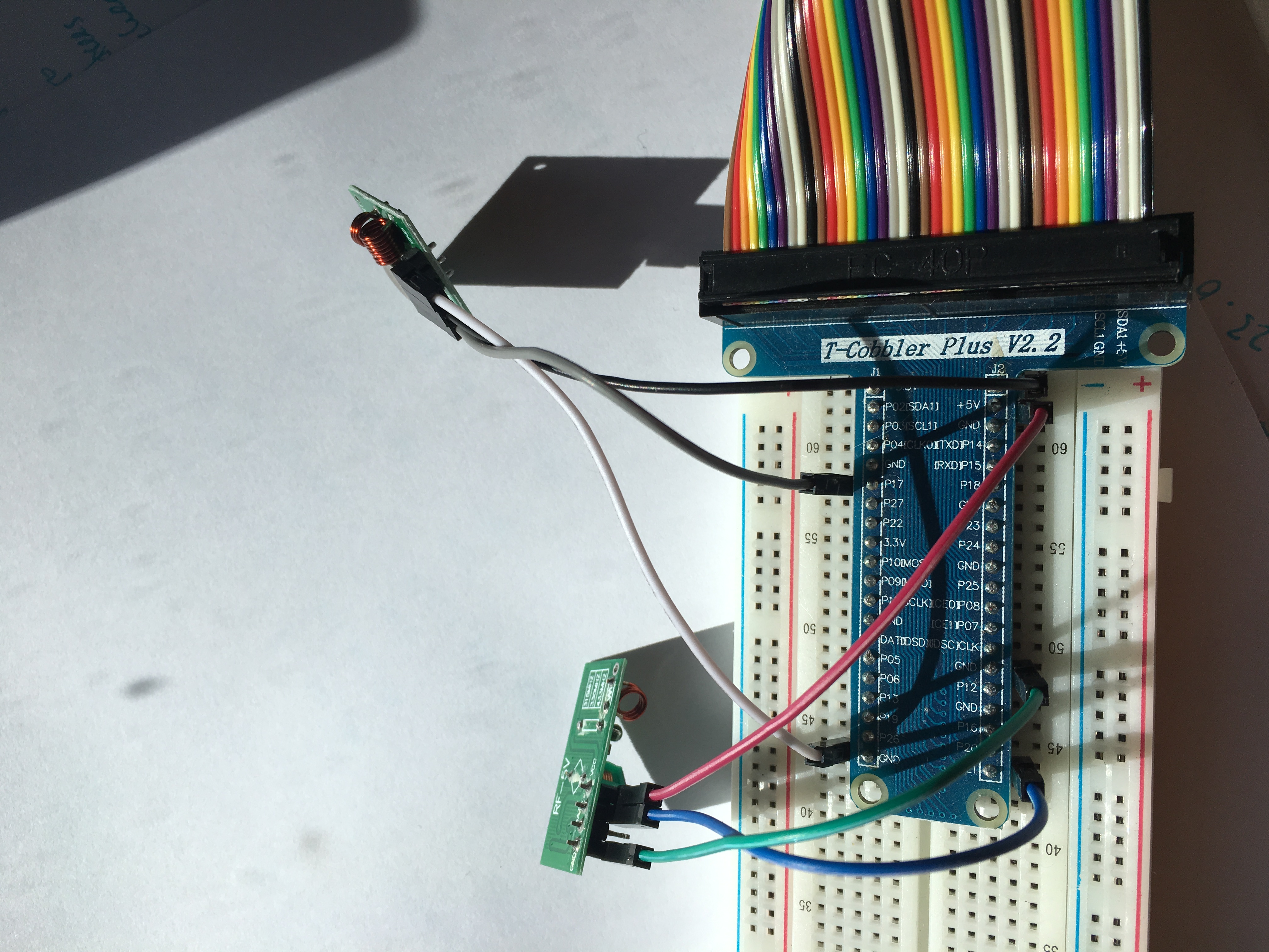
Lets have a look at the hardware. I have a breakout board from the Pi which helps.


The hardware is wired like this
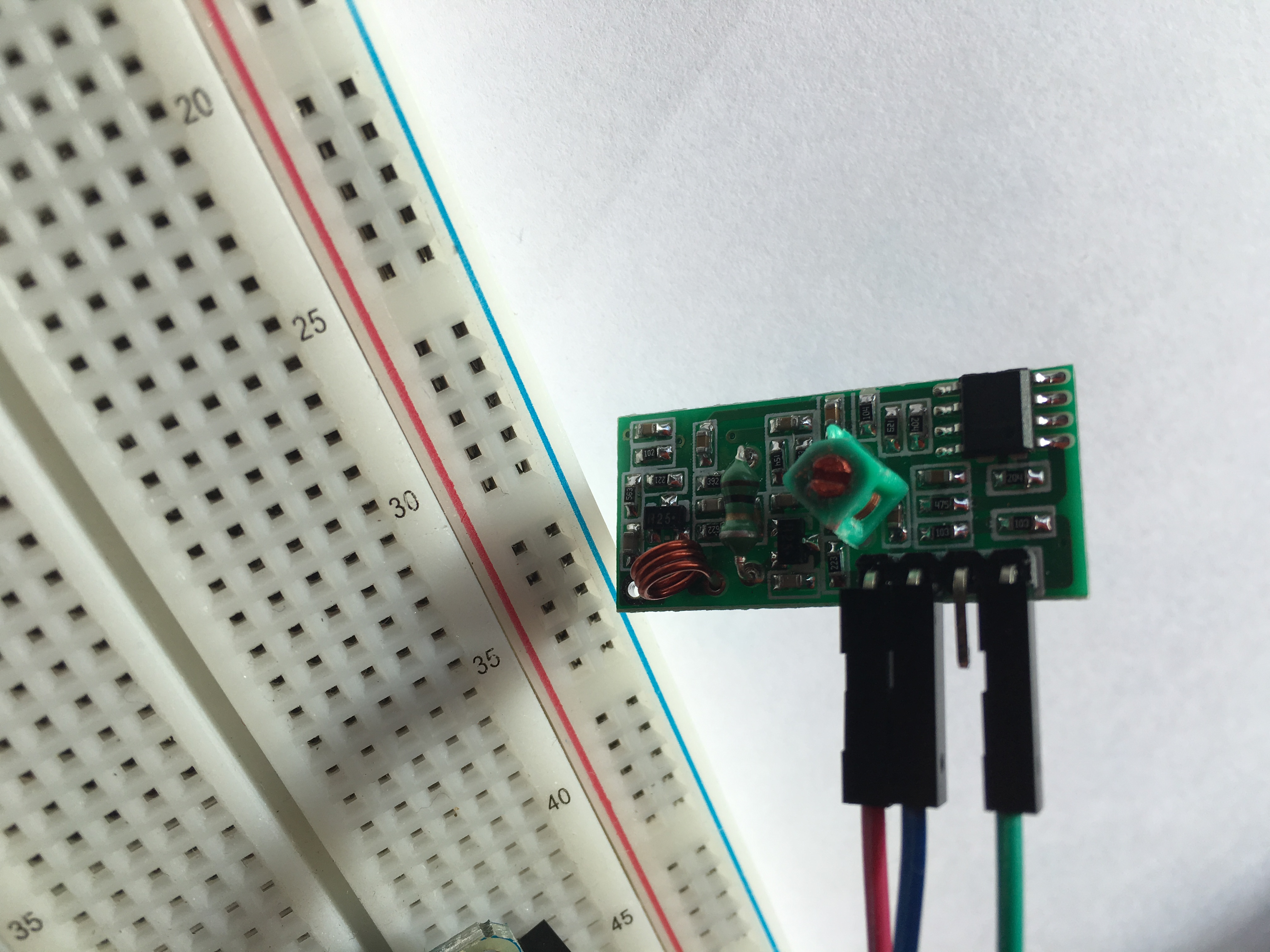
Receiver
– VCC – 5v (Black wire)
– GND – GND bottom left (white wire)
– DATA – P17 (grey wire)
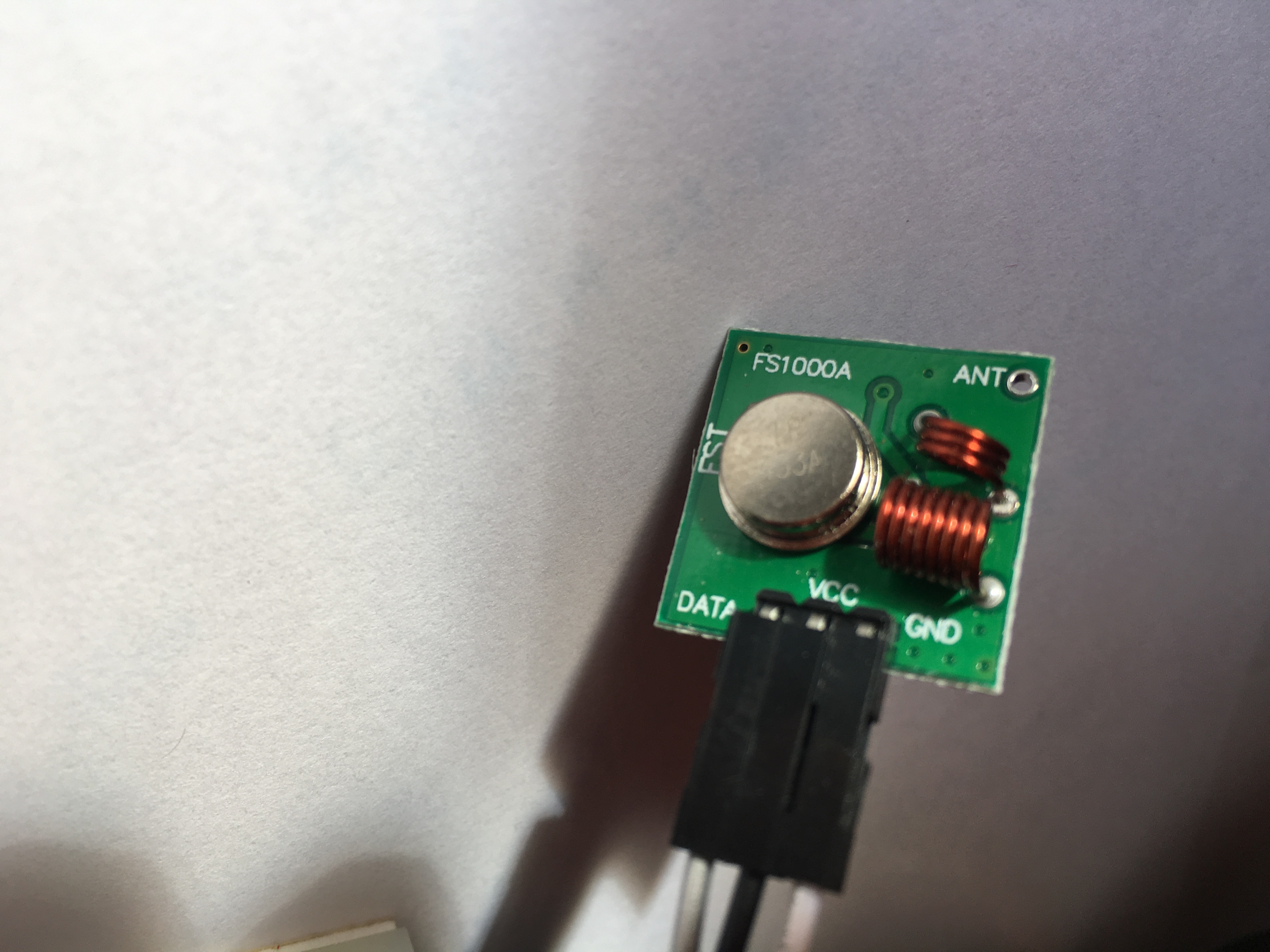
Transmitter
– VCC – 5v (Red wire)
– GND – GND middle (green wire)
– DATA – P21 (blue wire)
Now all wired up and software running.
Nothing works…. yet…. the investigation
Time to run RFSniffer
sudo /var/www/rfoutlet/RFSniffer
and as expected there is a blank screen. However clicking the BBSB remote seems to detect nothing even though the switch is turning on and off.
Well it seems I have not got what I want! I wondered if the GPIO was receiving anything. I found out I could install piscope and send the output to an X11 server. http://abyz.me.uk/rpi/pigpio/piscope.html. Some more installing of software Xming for the PC and pigpiod etc and I could then run piscope &. What I discovered was a Channel 21 was indeed receiving data but masses of noise so anything I might have been sending looked like it was lost in a sea and so RFSniffer was not getting anything different.
Some more googling and went here http://abyz.me.uk/rpi/pigpio/examples.html#pdif2__433D. Downloaded the 433Mhz Keyfob RX/TX software.
Getting this running indicated that the receiver was indeed getting data but that the format of the data was not Manchester encoding which is what this software is meant to do.
Getting the Bye Bye Standbye switches working
How do I find out what encoding does the BBSB use? Google again! It seems that BBSB is simple I found references to Home Easy Simple protocols. I tried using Pilight but could not work out how to configure it easily so tried looking further. Then found reference to KAKU OOK protocol. I eventually landed up installing rfctl from here https://github.com/troglobit/rfctl. The instructions are not for a newbie like me the command
sudo apt install raspberry-kernel-headers
was OK but then when I looked in /lib/modules there seems to be 2 directories. Which one? I eventually used 14.14.70+ and not 14.14.70-v7+. Took me a while to work out that I needed to do the following
cd /lib/modules/14.14.70+
sudo git clone https://github.com/troglobit/rfctl.git
but once past that simple bit the instructions are clear (but I needed to run as sudo)
cd rfctl/kernel
sudo make
sudo make install

cd rfctl/src
sudo make
cd make install
I have my BBSB set to A3 so trying the following worked a treat
this turns on
rfctl -p NEXA -g A -c 3 -l 1
and this turns off
rfctl -p NEXA -g A -c 3 -l 0
Now how to integrate this into Home Assistant.
When I Googled the remote model number WST-8500 and found the receiver model numbers are YCR-300,YCR-3500,WSR-1000,LCMR-1000,LCMR-300. Not sure if this is going to help in the future or not.
Integrating into a single command
The next step is to be able to run this command remotely from the main Home Assistant server as I will not be using the HA on the Pi and will stop Hass from running at boot time.
So for passwordless ssh from the HA server to the Pi I created some ssh keys using command
ssh-keygen
on the HA server while logged in as the homeassistant user. (it turns out that HA is running under root user and so the .ssh keys from root could make this work but instead made HA server run under the homeasssistant user).
Next step create a new user on the Pi, gave the user sudo privileges (sudo user mod -aG sudo <username> and copied the keys to the Pi new user
cat ~/.ssh/id_rsa.pub | ssh <USERNAME>@<IP-ADDRESS> 'mkdir -p ~/.ssh && cat >> ~/.ssh/authorized_keys'
next added an entry to the etc/sudoers.d directory for the new user giving access to /usr/local/bin/rfctl, dev/rfctl, and /home/<new user>.
Following this I created a simple shell script to allow running of the command for the switches in position A3 and A4 (I have only 2). The script is given execution privileges
chmod a+x onff4.sh so it can be run using
./onoff4.sh
I can now run the script from the HA command line logged in a the home assistant user like this
ssh -t <newuser>@<piaddress> ./onoff4.sh
